Research
Research Interests
- Experimental and Computational Fluid Dynamics (CFD)
- Rheology and Flow of Complex Non-Newtonian Fluids
- Suspensions, Multiphase, Displacements & Buoyant Flows
- Thin-Film Flow Modelling & Stability Analysis
- Coating & Co-Extrusion Flows
Current Research
Multiphase flow mixing with carbon capture application
This Ph.D. project, which is sponsored over 2024-2028 by a global leading energy company, focuses on understanding mixing between liquid and gas phases. The ultimate goal of the project is to design high-performance high-throughput carbon capture units to mitigate climate change and global warming impacts. Integrated experimental and computational approaches are adopted to tackle the multiphase flow problem in hand.

Figure: Multiphase flow mixing of liquid and gas which may be encountered in a carbon capture device.
Rheological characterization of slurries with 3D printing application
Currently, there are two Ph.D. projects being pursued on 3D printing topic in collaboration with the following organizations: Department of Wood Science and Engineering at Oregon State University (OSU), School of Civil and Construction Engineering at OSU, and College of Architecture, Arts, and Design at Virginia Tech. Specifically, we are interested in Direct Ink Writing (DIW) process in which a slurry or paste is injected (extruded) from a printer nozzle. Rheological characterization of non-Newtonian slurries (inks) becomes extremely important in predicting the printability of the mixture and avoiding product failure. Sample rheometry assessments include three-interval thixotropy test (3ITT), oscillatory shear test (amplitude sweep), and flow sweep hysteresis test. Project sponsor: Oregon State University Transdisciplinary Research Seed Fund Program (2024-2025).

Figure: Direct Ink Writing (DIW) process (left); fidelity assessment & printability diagrams (middle); common geometries used in rheological characterization of slurries.
Fluid dynamics investigation of valves (CFD & experiment)
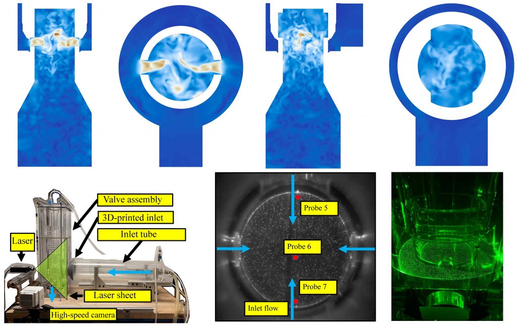
Flow within control valves is complex, specially for choke types with multiple entries. Despite their abundant use in pressure-reduction applications across various industries, fluid flow behavior within such valves is not properly understood. Failure modes associated with flow-induced vibration, erosion-corrosion, and cavitation remain as a long-standing issues with operation of these valves. In collaboration with local industry and through state-of-the-art experimental and computational techniques, we aim to understand and ultimately improve fluid flow inside valves. This project has been sponsored by Master Flo Valve (USA) Inc.
Turbulent Taylor-Couette flow control using superhydrophobic surfaces
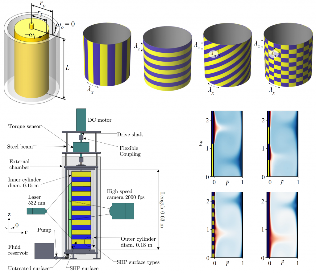
Secondary turbulent flows are commonly formed in centrifugal mixers (Taylor-Couette flow configuration). Once formed, these coherent structures can hardly be moved, leading to poor fluids mixing properties. Through experimental and computational techniques, our team has been investigating various superhydrophobic (SHP) surface patterns that can result in increased mixing while lowering the required torque and centrifugal power consumption. This project has been sponsored by National Science Foundation (NSF-CBET-1934121). Learn more here.
Displacement flows in inclined ducts
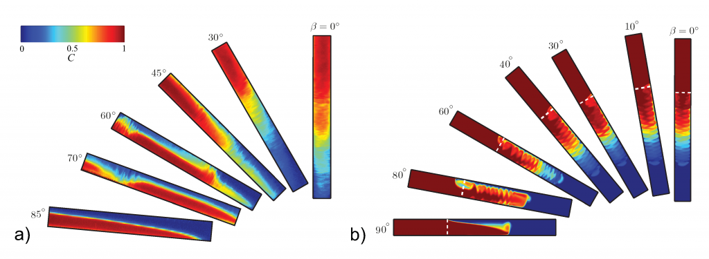
Displacement of one fluid by another is a fundamental problem widely observed in both nature and industry. Over several years we have been studying this problem in inclined geometries for both Newtonian and non-Newtonian fluids. The industrial motivation for this research comes from the processes present in construction and completion of oil & gas wells. Examples include primary cementing, hydraulic fracturing and gravel packing. Geothermal, Carbon sequestration and domestic water distribution wells are cemented using the very same techniques as in the oil & gas industry. The objective in well primary cementing is to hydraulically seal the newly constructed well to avoid leakage of subsurface fluids into the near-surface ecosystem. We study these flows through joint experimental, numerical and analytical techniques to finally design the displacement processes more efficiently. This in turn will reduce the environmental impacts while increasing the well productivity. The figure shows flow patterns observed in buoyant displacement flows in inclined geometry experimentally and numerically. Learn more here.
Flow of Suspensions with Non-Newtonian Bed Fluids
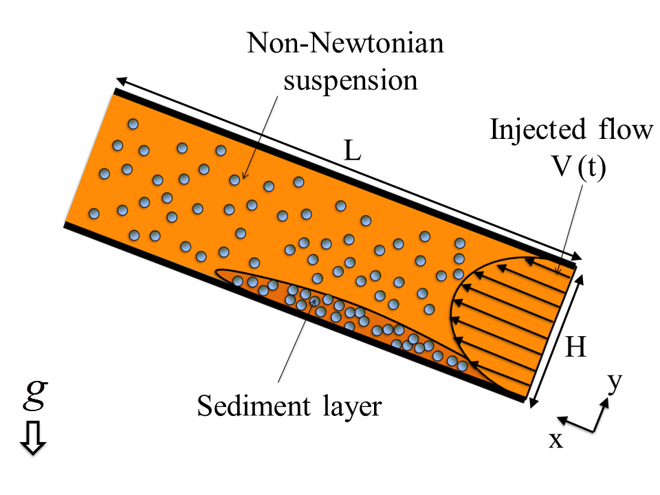
Suspension flows frequently occur in both natural phenomena (gravity currents, debris flows, lava flows) and many industries including oil & gas (hole cleaning, transport of cuttings and solids during drilling process, hydraulic fracturing, gravel packing), food processing, paint, mining, pulp and paper processing, etc. Non-Newtonian rheological effects are often prevalent. The geometry in which suspension flows occur are commonly pipe, channel or annulus geometries. We study the flow of suspensions through experimental, numerical and analytical techniques in order to find the most optimum rheological and flow conditions that cause the least amount of sedimentation throughout the process. Learn more here.
Fluid invasion into viscoplastic beds
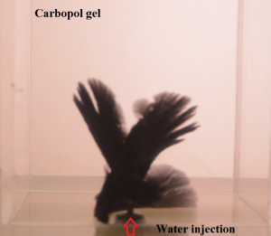
We are working on the fundamental topic of fluid (gas/liquid) invasion into viscoplastic beds with intentions to resolve the gas-migration problem in cemented oil & gas wells. Once oil & gas wells are drilled, the annulus space between the production casing and rock formation is filled by cement slurry. The slurry will then be left to set and solidify. During the solidification stage, formation fluids may enter the cemented annulus in the form of gas or liquid. This in turn, can create channels that provide an undesirable flow path of the reservoir fluids including hydrocarbons into the wellbore and near-surface environment. We aim to study this problem experimentally, computationally and analytically in order to finally design the cement slurry fluid such that it minimizes the fluids intrusion from formation into the wellbore. This will in return, decrease the environmental impacts and increase the well productivity. The figure shows the experimental snapshot of a liquid invading a viscoplastic fluid, mimicking the formation liquid migration towards the cement slurry. Learn more here.
Multi-layer coating and extrusion flows
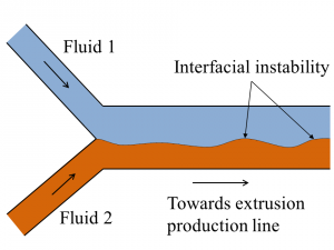
Two-layer flows are found in both nature and industry, e.g. coating and co-extrusion flows. At high flow rates inertial effects become increasingly important and a long-standing problem has been how to represent these effects simply in a way that remains faithful to the flow stability. Although resolved for single fluid flows years ago, extending the stability analysis methodology to multi-fluid flows has been evolved more slowly owing to the difficulties associated with the interfacial conditions. We aim to overcome these obstacles through flow modelling. The mathematical models developed and their implementation to a two-layer system enables us to predict the behavior of co-extrusion and coating flows more accurately by including the combined effects of surface tension, viscous, gravitational and inertial forces. By properly modelling the co-extrusion one can predict, and thus prevent, defects in the final product which arise due to the flow instability. Learn more here.
